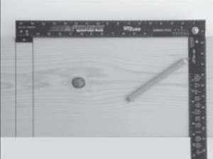
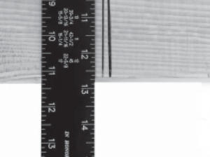
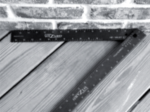
16″ ON CENTER LAYOUT
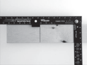
Mark first layout. Slide the Framing Wizard® until
tab is in first layout as shown above. Mark new
layout and repeat as necessary.
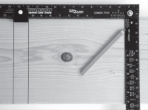
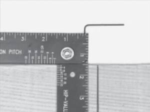
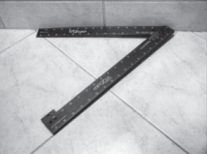
12″ ON CENTER LAYOUT
Place the adjustable tab in the channel of the Framing
Wizard where the edges line up with 10 1/2″ and 12″
as shown above.
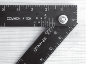
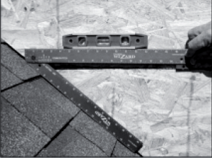
COMMON RAFTER LAYOUT:1
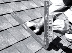
Simply adjust arm edge until it aligns with the desired
common pitch on the scale. The picture above is a
10 common pitch.
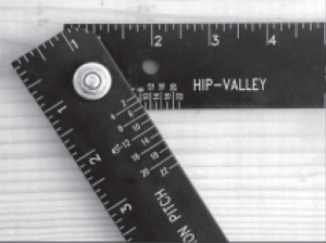
HIP/VALLEY RAFTER LAYOUT:1
Simply adjust arm edge until it aligns with the
desired hip/valley pitch on the scale. The picture
above is a 10 hip/valley pitch.
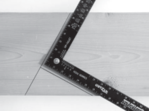
HIP/VALLEY RAFTER LAYOUT:2
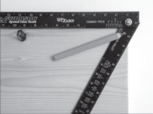
To mark for the double 45-degree bevel, first
place a single short mark at the corner of the rafter.
HIP/VALLEY RAFTER LAYOUT:3
Next, align the center of the hole in the arm
over and the single short line as shown.
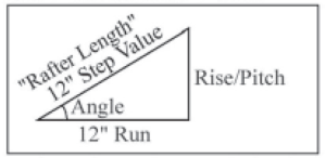
USING THE CHART 12″ STEP
Use these values to determine the length of a common rafter. The chart gives the rafter length for each 12″ of run for a given pitch. EX.For a run of 6’2″ with a 9″ pitch, rafter length is 6′ x 15″ (See 9″ pitch from the Chart) = 7’6″ plus add 2″ more to the rafter perpendicular to the top to get the complete rafter length.
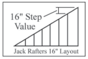
USING THE CHART 16″ STEP
The 16″ step value is the difference between two consecutive jack rafters for a given pitch. Once the common rafter length is known, simply subtract the value given for the 16″ step (On Chart) from the common rafter to get the first and longest jack rafter. Continue subtracting to get each jack rafter.
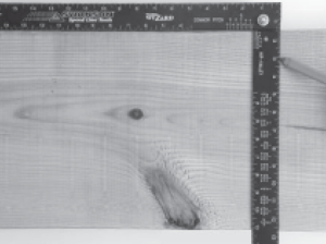
ADJUSTING BACK TO SQUARE:1
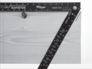
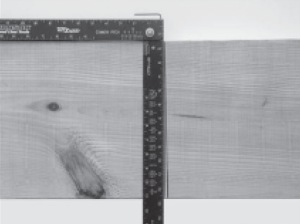
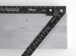
Open the Framing Wizard® arm as far as possible, place on a wide board and draw a single line.
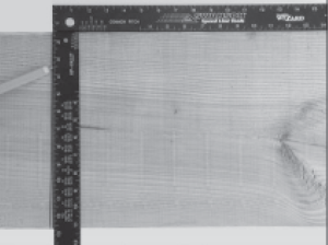
ADJUSTING BACK TO SQUARE:2
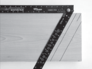
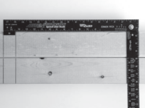
Flip the Framing Wizard® in the opposite direction, align the top of the arm to the first line and draw a second line.
ADJUSTING BACK TO SQUARE:3
Check that both lines drawn are in the same place. If there is a space between the two lines, continue with adjustment.
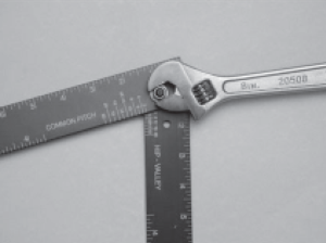
ADJUSTING BACK TO SQUARE:4
Place the included allen wrench into the setscrew and align the
top of the arm to the lines drawn.
ADJUSTING BACK TO SQUARE:5
Tighten or loosen the setscrew to adjust the arm until it is centered bewteen the two lines drawn. The Framing Wizard® is now square.
ADJUSTING THE ARM TENSION
The amount of tension applied to the arm can be adjusted by simply turning the lock nut, which holds the arm in place.


